Table of Contents
EduBRM
~~META: status = done &relation firstimage = :project:edubrm.jpg ~~
Great Global Hackerspace Challenge
About
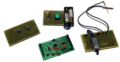
Aim of our project was to create an open platform for teaching electronic principles. Our target audience were students of elementary and comprehensive schools interested in this field. The main idea of the project is to provide modular design. One “mother board” can be extended with a set of “shields” which are used for particular scenarios. During the challenge we created three example shields and one debug shield for our purposes.
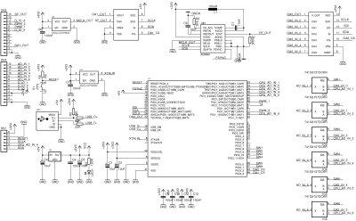
Mother board is based on ARM Cortex M3 chip (more exactly LPC 1343 from NXP Semiconductor), Direct digital synthesizer and Operational Amplifiers. This combination allows us to read 6 analog values from the shields, which can be very low, because they can be multiplied up to 32x. DDS generates frequency from 1 Hz up to 50 MHz in 1 Hz steps, which can be used for generating various signals or alternating current.
The first demo shield we create illustrates the creation of electricity using a dynamo and electrodes. These are made from different metals and can be plugged into lemon or a potato. Software reads up voltage and draws a nice graph.
Second shield represents a simple DC circuit with a battery, switch and a bulb. Edubrm application can detect whether battery and bulb are present and if the student has pressed the button. It also visualizes which parts of the circuit have power and which not.
Third shields can visualize voltages and currents in circuits with coils and capacitors. It can also switch between AC and DC power source so student can easily understand behaviour of these electronic parts while turning the power on and off.
Check the following video to get the idea how it works!
u662X7ndcCM
We also came up with ideas for lots of shields that could be used in other fields than electronics. Sadly, we were not able to implement them in time. To give some examples:
- shield with two speakers emitting the same soundwave but with different phase, student can use the microphone to find out that there's no sound in the exact middle of them, application would draw charts of signals to speakers and from the microphone (acoustics)
- shield that can read various amplified biosignals, like ECG or EEG (medicine)
- shield with dynamo and motor connected through gears, student can inspect the resulting voltage while changing the gear ratio (mechanics)
Detailed specification
hardware
- open-source (e.g. CC BY-SA)
- predefined module pinout, each pin having one specific purpose
- “mother board”:
- ARM processor (around 70 MHz)
- 1 or 2 generators
- 2 multiplexers
- 4 IC analog switches
- “shields”
- various components depending on purpose (e.g. switches, bulbs, resistors, coils)
- short-circuit protection
- overvoltage protection
- needs to be lowcost as possible but durable
software
- open-source (e.g. GPLv3)
- ability to analyze measurements by computing and visualizing measured values of voltage, current, power, frequency, etc.
- has to be able to simulate/emulate different conditions
- possibility of creating interactive quizzes / games
example shields/scenarios
a) basics - "how is electricity created"
  - electric field
  - electrochemic reaction
  - electromagnetism and measurements
b) simple circuit with battery, wires, switch and lightbulb
  -basic electric circuit AC/DC
  -theory and measurements
c) slightly advanced circuit with resistors, coils and capacitors
  - electronic parts R, C, L in AC/DC circuits
  - basic measurements
  - RC, LC measurements
d) advanced measurements on semiconductors
  - basic measurements on diodes > meaning of PN
  - measurements on transistors
  - operational amplifiers
e) much much more!
Pionout assignment
SPI:
SDI -27 - input
SDA -28 - output - ??
SCLK-29 - output - ??
FSYNC - 10 - output -1
OA1CS - 43 - output -1
OA2CS - 48 - output -1
SWITCHE:
SW1 -12 - output -0
SW2 -24 - output -0
SW3 -25 - output -0
SW4 -31 - output -0
SW5 -36 - output -0
SW6 -37 - output -0
AD:
CPU_AD_IN_1 -33 -input
CPU_AD_IN_2 -34 -input
CPU_AD_IN_3 -35 -input
CPU_AD_IN_4 -39 -input
CPU_AD_IN_5 -40 -input
CPU_AD_IN_6 -30 -input
OA2_OUT -32 -input
PWM:
PWM_1 -46
PWM_2 -17
DIO:
DIO_1 -1 - output -0
DIO_2 -11 - output -0
DIO_3 -2 - output -0
Links for inspiration
- analog switches:
- Opamp:
- DDS generator:
Interesting project of dataloger: http://www.x-io.co.uk/node/4
Nice theory blog with lot of tutorials : http://tronixstuff.wordpress.com/electronics/
Lady Ada lpc1343 tutorial : http://www.ladyada.net/wiki/lpc1343
nokia lcd ( SPI test ) : http://www.microsyl.com/index.php/2010/03/24/nokia-lcd-library/
http://www.arduino.cc/playground/Code/PCD8544
http://lpc1343codebase.googlecode.com/svn/trunk/
http://freaklabs.org/index.php/FreakUSB-Open-Source-USB-Device-Stack.html
http://support.code-red-tech.com/CodeRedWiki/CommandLineFlashProgramming
12→48 MHz crystal http://knowledgebase.nxp.com/showthread.php?p=4649
http://www.microbuilder.eu/projects/LPC1343ReferenceDesign/LPC1343_LPC1114_PWM.aspx
- 14851 - 8696 - 2650 - 365 = 3140
Schematics
GitHub, last commits
- add dd target to makefile by prusnak (2011/09/24 15:50)
- add charts to debug module as well by prusnak (2011/05/08 19:58)
- add hardware files by prusnak (2011/05/04 01:28)
- power on/off by prusnak (2011/05/04 00:24)
- more fixes by prusnak (2011/05/04 00:16)


