Table of Contents
Teslab
~~META: status = active ~~
What began as the (now archived) project Tesla Coil has expanded into a whole high-voltage-oriented room, located downstairs of the main Brmlab premises. If you're interested in a tour, or would like to join in, come stop by either during regular tuesday evening meetups or contact chido or mrkva.
The teslab and a few of our projects have been featured in an audio report on the popular-science website, vesmir.cz. You can listen to it here!
The Place
The small (~3x3m) room we occupy is situated below Brmlab, and was originally intended as a storage room until we came along. Now it serves as a place for all those experiments and projects that are too dangerous for people and/or equipment to be performed upstairs.
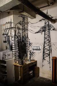
chido took it upon herself to paint the walls, so now the room also hosts the brmlab substation painting - pictures of it here.
We try to keep it as safe as possible (it's in our own interest after all), but it's still a dangerous place, we therefore advise visitors to heed our instructions and don't touch (or turn on) anything without supervision.
Our Tesla Coils
"Prcek/Cuketa" - the small one
The oldest (and longest functional) coil we have. Formerly the Tesla Coil project, it ended up being a tabletop coil with parts build from things scavenged around the lab.

"Porek" - the adopted one
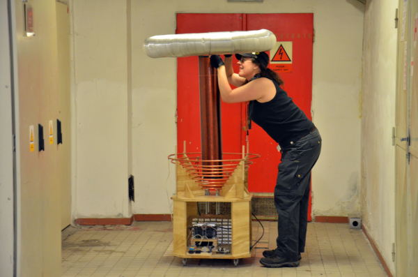
Porek is the largest coil that resides at Teslab. It was donated to us by its author, Filip, and remains unfinished, mainly for our inability to construct suitable capacitors for it. For pictures, go here. So far, it only consists of a primary and secondary coil, a socket and a toroid topload we borrowed for the Parsley coil before we made the octagonal.

"Parsley/Petrzlen" - the main one
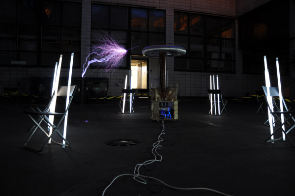
Petrzlen (or Parsley in English) is under ongoing development since summer 2013 by both mrkva and chido and is by now mostly functional. We regularly take it outside to play - if you are interested in seeing it in action, contact either of us.
Short description
This is the second largest Tesla coil currently located in Brmlab. The topology is well proven DRSSTC (double-resonant solid state tesla coil) design, with capability of audiomodulation.
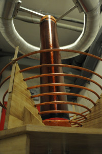
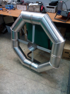
Secondary is 92cm tall, wound with 0.355mm wire (~2400 turns). Somewhat experimental octagonal topload made from exhaust fume ducts. Resonant frequency of secondary is approx. 59kHz.
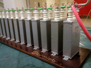
Primary side consists of 8×8 array of 1kV/0.5uF KPI-300-047 pulse capacitors made by ES Ostrava a.s. and 8-turn primary coil made of 10x1mm soft copper tube, with inner diameter 25cm, outer diameter 55cm. The coil is conical, with 45° slope. As switches on the primary side, we use a pair of 2MBI300-140 IGBT half bridge modules, rated 1.4kV, 800Apk. Primary voltage is regulated using old soviet 10A variac and connected on the H-bridge terminals through mains filter and voltage doubler with 400V/8.2mF electrolytic caps.
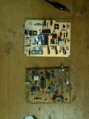
Driver electronics is custom-made using primary current feedback, fed into 4046 PLL IC, two stages of gatedrivers (first level is pair of IC gatedrivers boosted by the two discrete pairs of N/P MOSFETs. Output drives directly gates of IGBTs using GDT. The board is capable of both interrupted and CW mode of operation, with overcurrent limiting and audio modulation (untested yet).
Power electronics
Circuit diagram of the power electronics
Regulated output from variac is fed onto L,N,PE input connector, filtered using pi-filter, and rectified in voltage doubler. Ouput of the doubler is connected to two half-bridge modules using aluminium L-profiles, to minimize any resistance between large filtering capacitors and bridge. On terminals of each module are two 1.5kW 400V unidirectional TVS in series. Gate of the transistors are connected directly to the GDT output and are protected using 600W 18V bidirectional TVS. Between primary tank capacitors (C_PRI) and primary coil (L_PRI) are two ferrite toroids, one working as primary current feedbeck, another one as sensor for primary current limiter.
IGBT failing and subsequent rebuilding of the power electronics setup
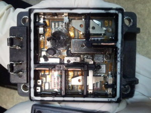 During testing of maximal input voltage capability of the coil, one of the IGBT modules failed. We gradually raised the variac input voltage up to 190V, which worked fine - the IGBT module failed during capacitor discharge, when the variac was turned to 0, probably due to an unexpected voltage spike (we never determined the exact reason). We decided to replace the old (and slow) 2MBI300-140 IGBTs with FF450R12KT4 Infineons. Several changes to the power electronics setup will be implemented, such as adding a pair of pulse 1.2kV 2uF IGBT snubber capacitors for filtering out voltage spikes faster, and replacing the aluminium L-profiles with copper profiles for less resistance. More updates on the new set-up will follow.
Driver electronics
Circuit diagram of the driver board (outdated) There were two issues with the board - at first, the current transformer inputs were clamped only to +5V and GND rails and when the current transformer generated more power then the whole board required, voltage rised above acceptable level and damaged the board. The second issue was caused by lack of stabilization of +15V to the UCC gatedrivers and (D9 zener was not placed on the board at all) and overvoltage damaged the board again.
After that, we've decided to do entire new version again - Circuit diagram is here
The driver circuit might look too complicated, or at least more complicated than other DRSSTC designs. The feedback from primary current sensing coil is clamped to 0/+5V voltage rails and fed directly to input of 4046 PLL IC. We've chosen 4046 C,R1,R2 (C7,R11,R12) values so the resonant frequency of primary circuit will fit within operating range of the 4046.
Other signal from current limiting coil is rectified using Graetz bridge from Schottky diodes, filtered and compared to reference voltage, if it is greater LM311 comparator (IC4) sets its output high, forcing interrupter output low, effectively stopping operation.
D-type flip-flop (IC3A) takes as input value from interrupter and as clock output from 4046 and is effectively synchronizing interrupter singal with feedback from 4046, preventing any hard switching.
Signal is then fed to pair of UCC27322(1) gatedrivers that were supposed to drive the GDT. This was however proven to be almost impossible - even at low interrupted duty cycle UCCs were getting really hot and worse - at maximum recommended input for UCCs (15V) the voltage across gates of IGBTs was only ~10V. Given the fact that those big IGBT bricks have gate saturation voltage approx. 8V, it was really dangerous thing to do - one small voltage drop below saturation level and total power dissipation on that IGBT bricks would destroy them. The final solution was to add a small H-bridge made of complementary MOSFETs that are driving the GDT. It works really nice, however when we've decided to raise the GDT driving voltage a little bit, GDT became saturated and had to be rewound. Now it works really nice - see the “Measurements” section!
Control and audiomodulation
sjcuu-wAry0
Parsley playing Popcorn (Hot Butter) MIDI at 80VAC input.
bvGfN5g3Wpg
Smoke on the Water
YsW2kKsj3ek
Final Countdown

Measurements
Finished version of gatedriver
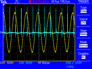
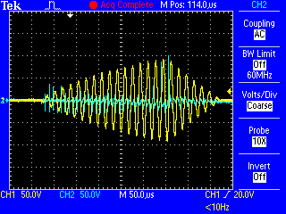
Testing current limiter feedback transformer
- CH1 is voltage across 1Ohm resistor directly in primary circuit
- CH2 is voltage on the 100Ohm loading resistor on CT output
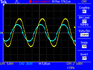
Measuring voltage ripple across bridge
- CH1 is voltage on the 100Ohm loading resistor on CT output
- CH2 is (DC blocked) voltage across bridge (farthest from filtering capacitors)
Yep, hard switching is a bitch, but after tuning phase-shift a little bit, output looks much nicer:
Measuring complete coil
- CH1 is voltage on the 100Ohm loading resistor on CT output
- CH2 is voltage on a probe hanging free in the air near topload
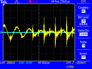
- CH1 is probe connected to the 30cm of wire in a room 8m away from the running coil. Coil was running at ~70VAC input from variac and was producing ~80cm sparks
- CH2 is unconnected
TODO (mrkva): more pri/sec measurements
Other Toys
Capacitors

HV Power Sources
LF94NCBnMwg
20kW HW power supply prototype: xbY9EZlj-3Y

X-Ray Machine
Marx Generator
Goal of this project is to build a small Marx generator. Marx generators are pulsed voltage multipliers, that can be used to experiment and play with voltage levels that are difficult to reach by other means. High voltage pulsed discharge also usually generates smaller EM pulse - another thing to experiment with. Marx generators can be also used as a power supply for plasma (and fusion) experiments!
chido would like to try using it in Project Biolab electroporation experiments.
We built our first working model, the Одуванчик (Dandelion).
Tci4LVx6fKA
vHX-fBujcJ8
Status/TODO list
find a safe place to operate this thing - due to EM interferences generated, typical hackerspace overfilled with RFi sensitive equipment is not an ideal place for a thing like this. It will be necessary to operate generator in distant or shielded area.Operating generator in the basement looks finegood high voltage power supply (~20kV DC, with decent current rating), maybe neon sign transformer? - Dual MOTs with voltage tripler- right now we're using rectified neon sign transformer- Our current generator has 14 100nF capacitors rated at 4kV~ / 9kV= connected with 1MOhm resistors. The repetition rate is still somewhat random - we need to make full-wave rectifier bridge first and maybe try using two resistors in parallel thus reducing the resistance to 500kOhm.
- We've made a new power supply with two MOTs in series and third one as a choke on the primary side. MOT output is connected to voltage doubler so effective output voltage is ~8-10kV.
Fun Stuff we Do
We do all sorts of high-voltage related experiments, here's some examples:
Inspired by this Hackaday how-to, we made our own Jacob's ladder: M1vqhQBX-z0
Prompted by the most remarkable (at least for a biologist) metabolic pathway of fructose, chido bought some and a series of experiments on cooking using high voltage ensued. These included (among a failed attempt at making popcorn and a more successful one at roasting marshmallows) making caramellized fructose using an electric arc. For a detailed recipe, see this handy how-to. 0PUFUCJJJa8
We've disemboweled a couple of microwaves, not letting the magnetrons go to waste: SqzK38Db5rk
And tried to make art: W1Rm8ebRZMg
Parsley viewed from inside a faraday cage, by bluebear nVrmPpIBkpg
Teslathon 2015
We participated in our first Teslathon with Petrzlen/Parsley the audiomodulated DRSSTC in September 2015, here are some videos by RayeR:
Czech and Slovak national anthems: KZ7dk_YSR6k
Final Countdown: LVKJkdjIEVg
Always Look on the Bright Side of Life; interrupted by a passing (and probably slightly terrified) car: kiRvEk1LVGI
Kraftwerk: vrfT556YXME


