Table of Contents
Brmlab LEDbar
~~META: status = active &relation firstimage = :project:ledbar-5.jpg ~~
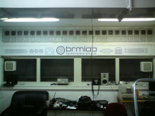
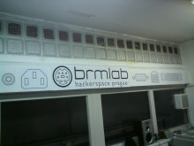
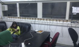
The rear wall of the main brmlab room faces the street around the building. There is a row of 23 square glass blocks at the top of the wall that are translucent and visible from the outside.
We would like to make a 23×1 pixel RGB display out of these glass blocks, showing cool animations and funky patterns 'round the clock, possibly also indicating open/closed brmlab status. It could be controlled by custom programs, over the net or interactively using e.g. a hacked music keyboard!
Possible Usage
- Indicator of brmdoor status
- Simple patterns - progress bar, Nightrider KITT-like animation, …
- Binary clock, morse code transmissions
- Simple rainbow - shifting, but only very slowly (e.g. barely perceptible if brmlab is closed, much faster if open)
- Fancy full-color animations - no limit for your imagination!
- MIDI keyboard control for interactive creative pattern-making (“play light”)
- Part of an interactive brmlab geocache
- 1D cellular automaton (modification of game-of-life or some similar random-patterns)
- 1D digital lavalamp (multiple blocks are slowly moving from left to right and backwards)
- see http://github.com/brmlab/ledbar for a little program for testing animations
- by adding few infra detectors react to the feet movements of the people going around
Status
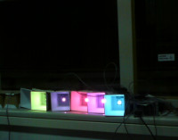
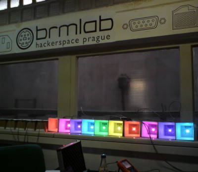
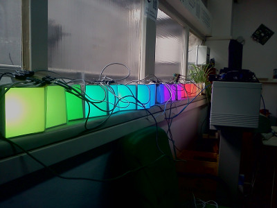
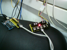
We have a row of 23 LEDs hooked up and working, connected to the sargon computer, where Python control software (rainbow or audio spectrum) runs in a dedicated screen.
Our current plan is to switch to smaller control boards with better LED interconnect, and build a second ledbar row so that we can finally move the current one to the ceiling. As of June 2014, it was set in motion again. (All these changes should be hardware-only, firmware + software compatible.)
Some media:
Technical Specs
Each glass block is illuminated by a single RGB LED node; 23 nodes are chained together with possibility of individual control.
Each node consists of three LEDs (R, G, B) with sufficient luminiscence. Each LED is hooked to PWM-capable control for smooth brightness control. The node needs to hold the LEDs in stable position and direct most of the light at the glass block, also dispersing it evenly.
The node chain needs to be hooked up to a microcontroller. The LEDs might require non-trivial current, so intermediate transistors are required. We need to PWM-control 23*3 = 69 individual outputs.
The microcontroller is connected to a computer (e.g. sargon) and simple control software.
Hardware
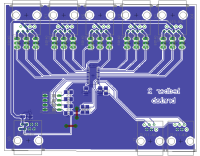
Version 2 is based on TLC59116 constant-current sink LED driver with I2C interface. TLC59116F could be also used, but circuit must be slightly modified (PNP → NPN + base pull-up resistors). TLC59116 allows up to 15 boards on one I2C bus.
In v2.0 (deployed), power distribution design is not ideal, current combination (RJ-45 + UTP cable) is not designed for high-current (up to 5 A) applications.
In v2.2 (in progress), more appropriate cables and connectors are used, and PCBs have lower form factor.
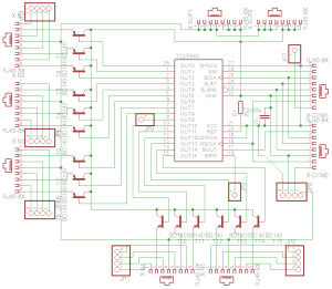
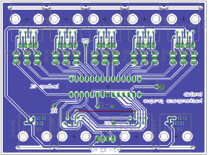
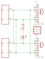
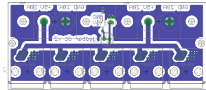
Schematics and boards are to be found in Git repository.
TODO / Roadmap
Current row, to be moved to the ceiling:
- [DONE] In all current LED boxes, replaced 4ohm resistor by 8ohm resistor on LED channel
- [DONE] Populating v2.2 boards
- [TODO] Překrimpovat the LED cables for v2.2 boards, other cabling
- [TODO] Build power distribution board for the v2.2 interconnect
- [TODO] Check shield compatibility with the v2.2 interconnect
- [TODO] Test the new v2.2 boards
- [TODO] Fix the current row on the ceiling
New row that will point inside the room:
- [IN PROGRESS] Prepare the LEDs
- LEDs plus breakouts bought, we will need to solder them on, measure resistances and build+attach some coolers
- [TODO] Buy components for another set of v2.2 boards (PCBs are already manufactured)
- [TODO] Build new LED boxes for the in-room row
- [TODO] Another Arduino? Or use one Arduino and put all LEDs on a single I2C bus?
Driver board v2.2 part list
Total: cca 220 CZK per board + shipping
Lessons Learned
- Verify your wiring. In twisted pair, if you have the wrong wire connected, for a single TLC it will work because the signal will induce to the other wire in the pair. For anything further a single TLC, the rest of the other wire will work as antenna and a lot of other mess will induce on it too.
- Verify your traces, and double check. The other problem was found to be due to etching bug - we have verified and fixed couple of interrupted trace on that board before, but missed this one.
- Arduino Wiring library should be supplied with only 7-bit address.
Software
The software is in Git: http://github.com/brmlab/ledbar
Two versions of firmware are available; standalone firmware with some builtin animations, and controlled firmware accepting raw RGB pixel value blocks on the serial.
The control software can either just show pixels on the display, or when given a device name (/dev/ttyUSB0), it will also send pixel values to the Arduino.
TODO / Roadmap
- [TODO] We need to tune the pixel brightness and color profiles. (depends on 4R → 8R red resistor change)
- [TODO] Port remaining C animations to Python
- [TODO] Improve the Python ledbar class to reduce redundancy in animation scripts
- [TODO] Make some fancy web UI
- [IN PROGRESS] Write and continue improving the computer control software
- [DONE] Basic control software: http://github.com/brmlab/ledbar
- [WIP] Network-based animation dispatcher.
- [SCRAPED] brmlab@blinkenlight screen runs network → arduino link, listening for 23*3 R,G,B byte sequences on UDP port 17740
- brmlab@blinkenlight screen runs ledbar control software
- Default: audio spectrogram of our main mixer speaker output; you can use alsamixer to switch it to microphone (brmlab ambient noise), but you will want to recalibrate the spectrogram to frequencies 100..2000.
- TODO: Proper multiplexing of default animation and network traffic, perhaps also status-based and noise-level based? (Show sound spectrum in case music is playing.)
GitHub, last commits
- Eagle files moved to eagle project by Nephirus (2014/06/23 18:14)
- equalizer: Fix high CPU usage by waiting a tiny bit in case of no dat… by pasky (2013/12/30 16:49)
- equalizer: Some old change I don't understand now by pasky (2013/12/30 16:49)
- equalizer: MIN_FREQ 30 -> 50 by pasky (2013/12/30 16:48)
- rainbow2d: Simplify by pasky (2013/12/30 16:48)
Further Expansions
Later, we can extend the display also to the storage room (extra 9-pixel row, and half of the second row visible too).
We might also try to split a single glass block to 2×2 pixel matrix, maybe cooperating with MoodyLight.
But let's start simple!
References
Historical Approaches
Version 2.0
- [DONE] Try out various kinds of LEDs for a single node
- We have tried http://www.gme.cz/cz/led-auto-rgb-2200-80-p511-869.html, but it (i) is common cathode, not common anode; (ii) more importantly, is not bright enough
- We have a power RGB LED from DealExtreme, but we do not trust DealExtreme enough for 23 LEDs operated non-stop, heavy duty, for at least few years.
- We have decided on http://www.gme.cz/cz/l-lxhl-hprgb-p511-558.html; we are capable of driving them by 250-400mA per channel, green is the one most difficult to feed with enough current. However, it seems there is minimal difference in brightness between 250mA and 350mA for any channel, so we will drive with reduced PWM now (and be prepared to increase it in case of too high resistance in wires etc.).
Material Needed
- (DONE) 24 RGB LEDs - 23 pixels, one spare. L-LXHL-HPRGB, 159CZK/piece.
- (DONE) LED holders - something sturdy and wide enough; we are cutting and gluing them from Club Mate boxes.
- (DONE) Wiring, transistors, resistors, etc.
- (DONE) PWM drivers
- (DONE) Arduino hooked up to a PC that controls the animation
LED Pledge
We need to get 24 LEDs (23 + 1 spare). The money required is CZK 150 per LED - it is a bit expensive, but it covers an extremely bright RGB LED, well visible through the glass even in bright daylight and from reliable origin. A bit of extra change is welcome to cover the supporting electronics (transistors alone cost 300CZK).
The LEDs you donated will have your nick written on the back of their boxes, to keep eternal memory of your contribution! 
| nick | LEDs | CZK amount | |
|---|---|---|---|
| pasky | 2 | 300 | (paid) |
| chido | 2 | 300 | (paid) |
| TomSuch | 4 | 610 | (paid) |
| niekt0 | 1 | 160 | (paid) |
| kxt | 2 | 300 | (paid) |
| AyM | 2 | 300 | (paid) |
| Kiki | 2.6 | 400 | (paid) |
| stick | 1.3 | 200 | (paid) |
| Nephirus | 1.3 | 200 | (paid) |
| biiter | 1 | 160 | (paid) |
| johny | 2 | 300 | (paid) |
| dzoe | 2 | 407+93 | (paid) |
| AxTheB | 1 | 160 | (paid) |
Total LEDs sponsored: 24
LEDs to go: 0
Sargon donated brmduino + FTDI.
Version 1
Sargon arranged TI samples of TLC5940. These are fancy serial-controllable, daisy-chainable LED drivers, each has 16 PWM current sink outputs. Each output is hooked up to the base of a PNP power transistor (part TODO), with LED cathode on the emitor. TLC current is limited to less than 10mA per channel using a 2k7 resistor on the current control pin. 100nF bypass capacitor per chip.
We need five TLCs to drive 23 RGB LEDs; we have a bunch, slightly less than we need. They are very fragile if too much current is drawn or there is bad connection where there shouldn't be, so we need to monitor them carefully anytime a change in circuit is made. During development (probably mostly due to low-quality breadboard), we destroyed about six pieces.
We already had all five TLCs set up on a breadboard, daisy chaining set up and working transistor drive.
Connectors: We use RJ45 connectors and ethernet cables for all interconnects. Should handle the currents fine and it is robust, easy to get and quick to crimp.
ledbar v2: ledbar.sch ledbar.brd
~~CL~~
ledbar DC interconnect v2: ledbar-dc.sch ledbar-dc.brd
~~CL~~
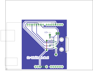
ledbar brmduino shield v2: Eagle files
~~CL~~
Current is now sourced in ATX supply. We consider replacing it with: http://www.djoro.cz/store/goods-G583---.html
Single uC
69 I/O pins is a lot. We will need to separate the outputs to segments (“cycles”) and also have one pin per cycle to switch between them. And rely on persistence of vision; we need to have at least 50hz frame-rate (i.e. all cycles finishing in 1/50s).
Classic charlieplexing probably will not work well with PWM at all. But with just five cycle control PINs required, something simpler could work nicely:
PWM0 o-*--(LED)----.
       |           |
       `--(LED)--. |   (LED) is
                 | |   transistor
PWM1 o-*--(LED)--+-*   plus LED
       |         | |
       `--(LED)--* |
                 | |
C0 o-----------|<  |
               GND |
C1 o-------------|<
                 GND
Microcontrollers generally do not have interestingly large number of hardware PWMs, but since we will be doing little else than driving the LEDs in our software, we can simply do the PWMs in software with more than enough resolution (8-bit ideally, but 5-bit would be probably already fine). E.g. ArduinoMega2560 has 54 output PINs, so just two cycles per frame would do, with some spare time to receive pixmap updates.
Price for seeeduino mega: ~900CZK. Plus: Not much soldering required. Single board = easy debugging. Minus: Relies on POV (can flicker slightly and such). Limited time to receive pixmap updates. *Huge* amount of *very long* wires, operating at high frequencies = hard debugging. High price.
Many uC
Each few pixels will be controlled by a separate microcontroller. All LEDs will be lit at once. The microcontrollers will share just a data bus (e.g. TWI).
The cheapest we can go is probably ATTiny26L, single microcontroller can operate three pixels (12 outputs). One uC would operate just two pixels = spare pins + time for serial-TWI interface.
In this case, it would be probably worth it having a PCB fabbed too.
Price for 7 microcontrollers: ~210CZK. Plus: Low price. Few wires = easy debugging. No POV reliance. Much less sensitive to pixel reprogramming interference. Minus: A lot more soldering. Many boards = hard debugging.
Many DAs
Like many uCs, but instead of microcontrollers with software PWM, use I2C-controlled digital-analog converters.
example: http://thingm.com/products/blinkm
DMX way
do it compatible with leading protocols in lighting control ..DMX and ARTnet
E.g.: http://response-box.com/rgb/wp-content/uploads/2009/06/diy2schematic.pdf
TODO: So how it works?
