Table of Contents
Transcranial direct current stimulation - tDCS
Transcranial direct current stimulation is a type of nonivasive cortical modulations technique witch use low DC current in order 25-80uA/cm2(more in HD-tdcs) via skalp electrodes to change resitng potentials of neurones.This chanages depend of polarity of stimulation = orintation od el. field to the neurones,the anodal (+) stimulation increases the neuronal excitability and Cathodal (-) neuronal excitability.When positive stimulation causes a depolarization of the resting membrane potential, which increases neuronal excitability and allows for more spontaneous cell firing. When negative stimulation is delivered, the current causes a hyperpolarization of the resting membrane potential. This decreases neuron excitability due to the decreased spontaneous cell firing.TDCS also have neuroplastic effect Anodal tDCS could induce long-term potentiation (LTP) through increased pre-synaptic activity coupled with postsynaptic depolarisation; conversely, cathodal tDCS could induce long-term depression (LTD) through reduced presynaptic discharge and postsynaptic hyperpolarisation.
Safety considerations for tDCS
Numerous studies verify that low-intensity transcranial stimulation is safe for use in humans and that it is linked with only rare and relatively minor adverse effects (Poreisz, Boros, Antal, & Paulus, 2007). tDCS does not elevate the serum levels of molecular markers of neuronal injury such as neuron-specific enolase (Nitsche & Paulus, 2001) or N-acetyl-aspartate (Rango et al., 2008). Furthermore, both contrast-enhanced MRI and EEG studies have found no pathological changes associated with application of tDCS (Iyezr et al., 2005; Nitsche, Niehaus et al., 2004). Additionally, no instances of epileptic seizures caused by tDCS have been observed in humans (Poreisz et al., 2007). In fact, pulsed transcranial stimulation has been correlated with an antiepileptic effect in rats (Liebetanz et al., 2006) and a previous tDCS study in patients with refractory epilepsy did not show an increase in seizures or EEG-epileptiform discharges (Fregni, Thome-Souza et al., 2006). The most common side effects observed with tDCS are mild tingling (70.6%), moderate fatigue (35.3%), sensations of light itching (30.4%), slight burning (21.6%), and mild pain (15.7%) under the electrodes (Poreisz et al., 2007). Less commonly, some subjects report headache (11.8%), trouble concentrating (10.8%), nausea (2.9%), and sleep disturbances (1.0%) (Poreisz et al., 2007). Skin lesions in the form of burns following administration of tDCS have been reported (Palm, 2008). Visual sensations associated with turning the stimulation on or off have occurred in a small number of cases, but this can be avoided by slowly changing the current level at the start and end of stimulation. tDCS delivered at a level of 2 mA and administered according to current stimulation guidelines (Nitsche, 2008) has been shown to be safe for use in both healthy volunteers (Iyer et al., 2005) and patients with neurological injury (Boggio, Nunes et al., 2007). Using a rat model, researchers investigated the safety limits of extended cathodal tDCS and found the charge density threshold to be two orders of magnitude greater than the charge currently administered in humans (Liebetanz et al., 2009). The safety of tDCS use in pregnant women and children, however, has not yet been investigated.
Step bay step way to understaning a tDCS
Stimulation current
In studes you find value 1 or 2 mA but what this tell you about effect of stimulation? Hard trouth is : almoust nothing ,without furteher information is this value useles.You need this value to count other more precize data.
Current density on electrodes
What this means, how to count it
This means current from the device devided by surface volume of electrodes.Moustly write in this manner uA/cm2 or mA/cm2 in some sudy you may find A/m2.
- uA means 0,001 mA
- to count current desity you need surface area and current
- for istance electrode 6x6cm have 36cm2 surface and with 1mA current source will have a current density 1/36= 0,027mA/cm2 =27uA/cm2
- there are 2.54 cm in one inch, therefore a 1” square electrode is 2.54 cm x 2.54 cm = 6.45 cm2
- electrode size in studies is about 15-100cm2 (for standard tdcs) in most of them 25-35cm2
Current density in electrode and safety
Studies have been completed to determine the current density at which overt brain damage occurs in rats. It was found that in cathodal stimulation, a current density of 142.9 A/m2 delivering a charge density of 52400 C/m2 or higher caused a brain lesion in the rat. This is over two orders of magnitude from what is currently being used. (14,2mA/cm2 ) The current density produced by present tDCS protocols ranges between 0.029 and 0.08 mA/cm2.It seem like safety measure not strict limit.Some experimental HD-TDCS to use 500uA/cm2 and test even 2000uA/cm2 withot harm ( but there is necessary to use special electrodes, gels and skin preparation).For normal tDCS is be good not to exceed 80uA/cm2 until be aviable more info about safety. We must also distinguish dangerous current density for the brain and the skin. Higher current density does not necessarily mean that the effect will be stronger. *needed more info about this 14,2mA/cm2 the validity of this information is very limited if we not know precize methdology of measurmnet the change in value can be few orders!!
*i test 318uA/cm2 for 20min (3,14cm2 , 1mA , EKG electrode , skin preparation ) without any poroblem ,skin by sligtly red by increased perfusion , the reddnes is disapear after cca 15min
Current density in electrode and effect
Anode +
Brain function under the electrode site is enhanced by roughly 20 to 40% when the electrode current density exceeds 40 µa/cm2 (260 µa/inch2).
Cathode -
reduces brain function under the electrode site by 10 to 30% at the fore-mentioned current density.
- this is very oversimplified !!! read further section for more info
- without information about placemet and size of electrode is this value almosut useless
The brain-stimulating electrode is called the active electrode, whereas the circuit-completing inactive electrode is called the reference electrode. In most of the studies, the reference has been placed over the contralateral orbit (above the left or right eye) to avoid negative effects from it. However, the studies never looked at the inhibiting effects that the reference electrode might have had on the prefrontal lobe. Some recent studies and in particular a study by Nitsche, et al., (2007) show that it is better to have a small stimulating electrode and large reference electrode. electrodes effect must be considered as a whole, the reference electrode always affect the active one larger reference electrode minimalize the unwanted effect,current density below 27uA/cm2 is in some studies considered functional unefective.
- this also not entirely true, it is oversimplified read further section for more info
- my recomandation is use for the return electrode current below 20uA if it possible
- Nitsche and Paulus found that a minimum current density of 17 µa/cm2 was needed to excite motor neurons. Studies involving other regions of the brain have suggested that 20 to 25 µa/cm2 are needed to excite neurons under the electrode. One depression study using anodal stimulation at F3 noted alleviated depression using 1 mA into a 35 cm2 electrode (28 µa/cm2). Iyer, et al., observed that when stimulating the left prefrontal cortex there was no effect on verbal fluency with a 1 mA current, but significant improvements at 2 mA (current density of 20 µa/cm2 vs 41 µa/cm2). Two depression studies by Boggio, et al., 2007; Boggio, et al., 2007) also used 2 ma.
- the excite is very vague name i not shure what this means
- is only for electrodes not cortex so the info means only if you use they electrode configuration you see this effects , for other areas and configuration the values may be very different
Edge effects
The high current density at an electrode edge is generally undesirable for safety reasons and may increase sensation during transcutaneous stimulation.
Theory
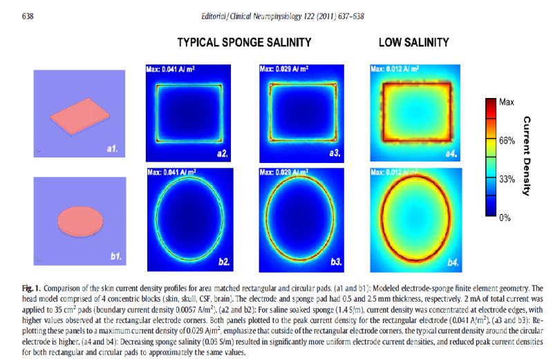
study:Cutaneous perception during tDCS: Role of electrode shape and sponge salinity
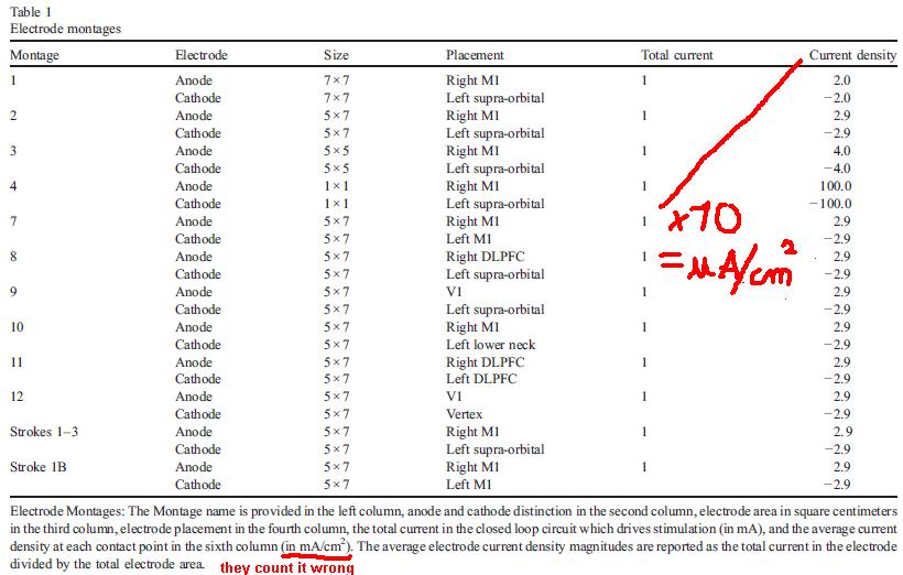
- WARNING in many studies scientist count wrong so read it carefully
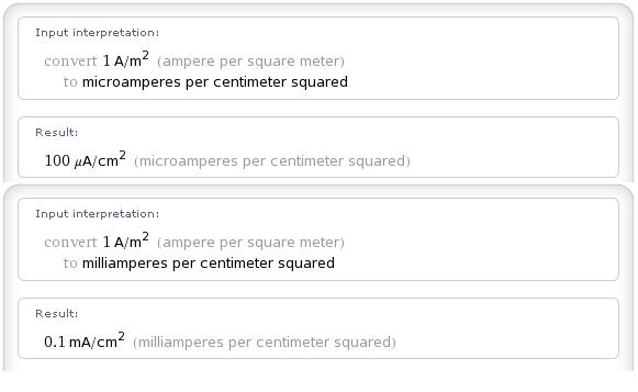
- if they want it in A/m2 that value is be 0,57 not 0,0057 its be better use 57uA/cm2
- this 0,041A/m2 is in real 4,1A/m2 this means the max in graph is 410uA/cm2 (290uA/cm2,120uA/cm2)
Practical implications
- decrease sponge salinity
- avoid sharp edges
Planned improvements to the device/protocol
- rounded edges or circular electrodes
- lower salinity = less cutaneus preception but higher resitance
- idea: electrode isert smaller than sponge can partialy lowering edge effect but higly depen of salinity
Current in top of the cortex
On with parameters depends current on top of the cortex and how large it is.
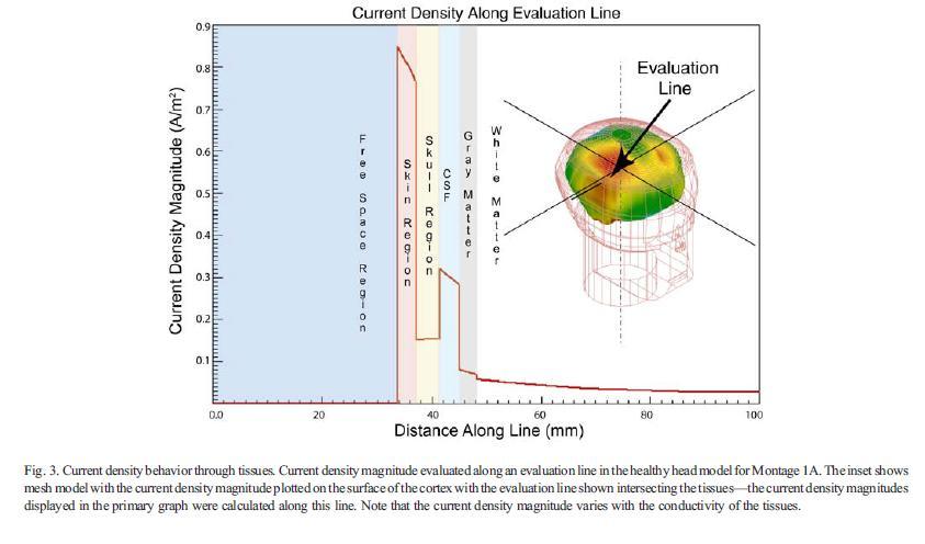
After current goes tough skin,skull nad CSF is much lower and homogenous that in electrode
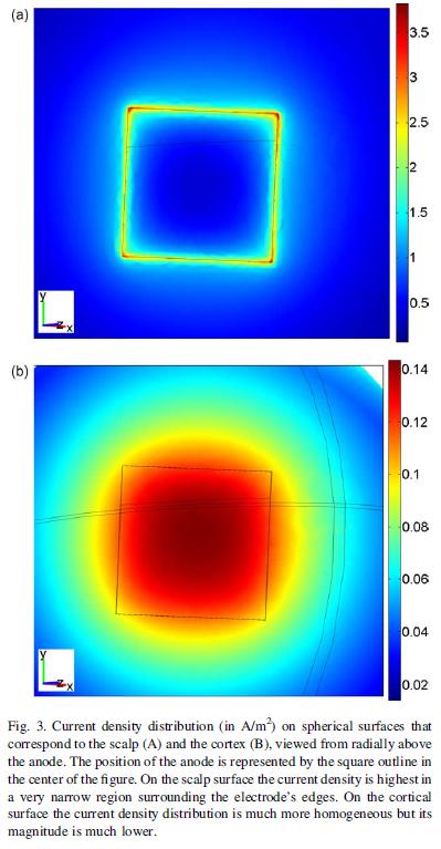
Study:Modeling the current distribution during transcranial direct current stimulation
- its a very simplistic spherical surfaces model this limits its acurracy
- look at current density due the edge effect of electrode is in cornes as high as 350uA/cm2 ,in cortex is max 14uA/cm2
Study:Transcranial direct current stimulation: A computer-based human model study
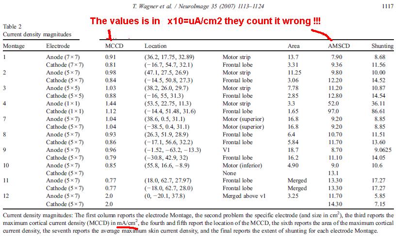
- *100=in uA/cm2
- good only for basic idea
- its showes some max not normal counted form area and current (max 79 nor 28 uA/cm2 on skin)
Role of size and imput current to current density on top of cortex
Study :What does the ratio of injected current to electrode area tell us about current density in the brain during tDCS?
Role of size and imput current to current density on top of cortex - notes
- only very basic model ,but good for understanding principes
Shunting
Large part of current is shunted by skin and also by lower level by skull and CSF. The ammount of current reaching cortex is depend of current density on electrodes its sizes and placements nad also of skin a skull thickenes. Current models dount count with skull anisotropy of conductivnes becouse is very hard get data for this model by MRI (it posible use CT). * individual male scalp and skull thickness variation, which can be as high as 58% and 34% of the average, resulted in up to 76% and 20% changes of the peak brain E-field, respectively
Study: Study:Transcranial direct current stimulation: A computer-based human model study
- shunting value means how many times is current in the cortex lower than in skin
- To quantify the shunting effect, we divided
the average maximum skin current density by the maximum cortical current density, where the average maximum skin current density was defined as the current density magnitude on the skin for which at least 0.5 cm2 in area was covered and which was not confined to the electrode boundary edge effects
Basic rules (for orintational values look to studies)
- smaller electrode have = more shunting
- electrode close together = more shunting
From one test: Electrode density in the cortex, i try to count difference of current density with this configuration nad standart 35cm2 pads (its only orientational) EKG electrode 3,14cm2 ,1mA , 318uA/cm2 ,+ on L-DLPFC and - on FT10 (left temporal below the hairline)
Role of size
- normal 8,7uA/cm2
- HD 21,5uA/cm2
Inresiting is current desity on electrode is be 11,21x higher but current density on top of the cortex only 2,47x This also means the current density is be the same like in 2,5mA with standart 35cm2 pads.
- The accuracy of these data is limited by several assumptions that were built into the model, such as the layered spherical geometry and the conductivity values used. However, since we are only calculating ratios (e.g., by what factor should the current be reduced when the electrode area is halved) as opposed to absolute values (e.g., what is the current density value at the target point), the results should not depend too strongly on those assumptions
Shunting
- only a very rude aproximation
- normal 8-9 uA/cm2 max
- HD 12-13uA/cm2 max
If we consider size and shunting effect the current density will be only 1,5 higher than in standart 1mA/35cm2
Implants
In discusions on the net is apper idea use some implants to tDCS.There is many options easiest is usage of microdermal implant materil is may be problem ,titan is seem posile but need testing.From my point of view is adventages not overcome the risks in sub dermal implant is be focality the same.Another options (my idea) is drill hole to the skull but not whole way trught pus some lectrode in nad isolator of top of it this is may increase focality and lowering needed current.Last option requied electron direcly in brain or in top of it hereis risk much grater.Probably best in this case is be used some electrode array.Device can have inductive recharge or contact on the skin.Main problem is infamatory response from body cause bad healing and need to remove implant and many others.So in short is posible but current state is not worth a risk becouse wee not know much about effect of stimulation yet.
Hi-frequenci currents ,inereference currents
- need more close look to it , if it work may provide better targeting, deeper stimulatin and large reduce in skin iritation.
- betrer for CES than for tDCS
Current distribution in the brain
In previous part we considered cortex mainly like a plane and white matter like have same conductivyty on all places for uderstanding next parts we needed more precize models,i start with easiest less complex/acurate ones.
Cortex folding
Know folding is very important becouse change the current distirbution and effect of tDCS mainly depends on orientation of neuronal structures to the DC vector . For now is not looking good for DIY tDCS projects this sentence desciping problem prety well: Individual variability of the human cerebral cortex is a source of both fascination and frustration.
- Folding patterns are relatively consistent in some regions (e.g.,the central sulcus) and much more variable in other, regions, including much of prefrontal and parieto-temporal cortex.
- main sulci map
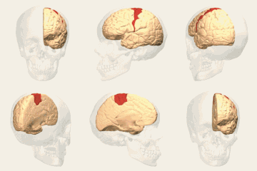
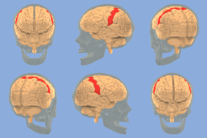
- central sulcus , motor cortex
- M1 area 4 position in the sulcus (usefull for radial/tangental field optimalization)
Interidividual variabality
- 50 brains of the ICBM database processed by BrainVISA after alignement in Talairach space
- some part is more variable than other this info cam be used to aproximate the field orintation to neurones on this areas
I searching for more maps of folding variabylity
Averaged MRI models
Give only very limited info , if be better to compare many subject MRI and look for similarity nad variablity (idelay find models of this variabylity).
Individual MRI model
Best is be have personal MRI model this give info about folding and also skull and skin thickness.For DIYers is imposible scan MRI but there is a option at least in EU if you participate in some research you have right to get data of your own scans. SumsDB (Surface Management System Database) and WebCaret Online Visualization BrainMap fMRI database
- new problems:area/folding,area size variability,folding fuction changes,connectional variability
- Probably ends up with trail and error style for eatch subject. :(
White matter conductivity anisotrophy
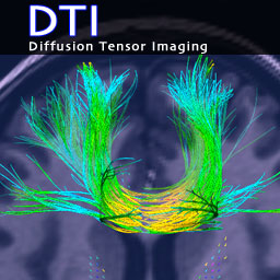
New models must count with anisotrophy of conductivyty of white matter caused by neuronal fibers to measure this is used technique called Diffusion tensor imaging (DTI) its a kind of MRI in some papeer named also DT-MRI.
The current flow generally follows the path of least electrical impedance. Consequently, compared to the isotropic model, current flow along theWMfibers in the anisotropic model is denser and follows the fiber orientation. In some cases the channeling of current along WM fiber tracts increases the local E-field strength, but in other cases this effect is offset by the lower impedance along the fibers, leading to reduced E-field strength. The current may steer away from segments of increased impedance resulting from the passage of WM fibers perpendicular to the current flow. However, when current comes across wide stretches of fibers perpendicular to its flow, the current cannot steer away and is forced to cross this high impedance barrier, resulting in high E-field magnitude. Thus, increased E-field strength in the anisotropic model compared to the isotropic model can result from either concentration of current flow along WM fibers that is not offset by the low impedance along the fibers, or from increased impedance for current flow perpendicular to WM fiber.
- the same is be for cortex neurones orintation (fibers is smaller but current higher)
Computational models
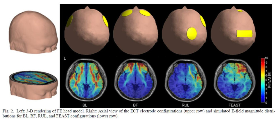
more info about variables in and of this study: Regional electric field induced by electroconvulsive therapy in a realistic finite element head model: Influence of white matter anisotropic conductivity
HDTargets (comercial)
Bonsai (write them they send back password)
Metods
The spherical and simplified geometry models do not fully account for tissue inhomogeneity and anisotropy, and the complex geometries of head tissues, including orifices in the skull such as the auditory canals and the orbits.
Concentric sheres models
low-resolution realistically-shaped representations
MRI based models
MRI and DTI based models
Regional Electric Field Induced by Electroconvulsive Therapy: A Finite Element Simulation Study
- its ECT not tDCS but current ditribution may be the same only field density is be much lower
- they used MRI+DTI :) but here is big limitations of this study :( electrodes as point sources ,MRI was only acquired for the portion of the head
- can good model but this is very limited they dount read how large effect is have size and palace elctrode to shunting and current to the cortex,also lower shunting by partial head model not add much to acuracy
Regional electric field induced by electroconvulsive therapy in a realistic finite
element head model: Influence of white matter anisotropic conductivity
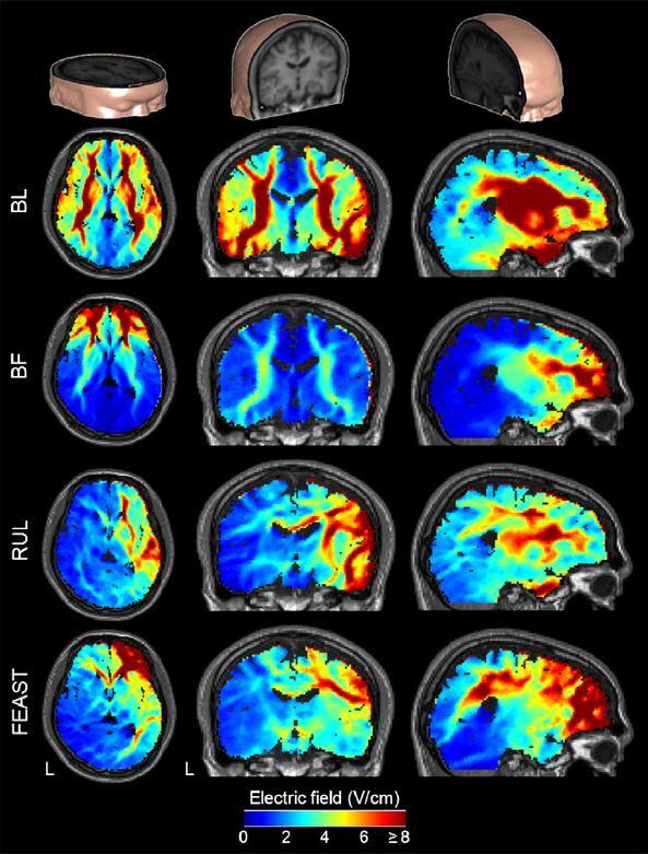
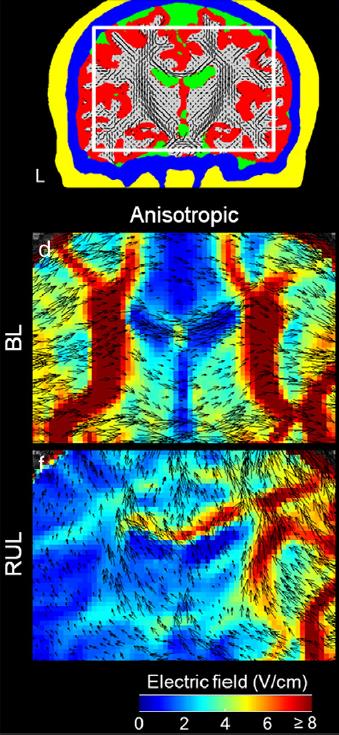
- 800mA (5 cm diameter),(2.5 cm×6.3 cm),(2 cm diameter)
- data was only acquired for the portion of the head
above the level of the auditory canal
- despite the higher current density in CSF-filled structures, the E-field magnitude there is relatively
low (blue color) due to the high conductivity.
studies to find: Our and other groups have previously incorporated tissue anisotropic conductivity in models of electroencephalography and magnetoencephalography (Gullmar et al., 2006, 2010; Hallez et al., 2008, 2009; Haueisen et al., 2002; Kim et al., 2003; Lee et al., 2008, 2009a; Marin et al., 1998; Rullmann et al., 2009;Wolters et al., 2006), transcranial direct current stimulation (tDCS) (Lee et al., 2009b; Oostendorp et al., 2008; Suh et al., 2009, 2010), deep brain stimulation (Butson et al., 2007), transcranial magnetic stimulation (TMS) (De Lucia et al., 2007; Thielscher et al., 2011), and electrical impedance tomography (Abascal et al., 2008). These studies demonstrate that anisotropic conductivity of the brain tissue can have a non-negligible effect on the electromagnetic field solutions.
Rescaling the current from Sadleir et al.'s (2010) and Parazzini et al.'s (2011) anatomically-realistic tDCSmodels and converting current density to E-field strength, the average of their reported median values is 2.5 V/cmand 2.7 V/cm, respectively.
Information
Current
A/m2 ,mA/cm2 ,uA/cm2
Field
V/m ,V/cm study comparing head models for TMS found a ~51% increase of the maximum E-field strength in the anatomically-realistic model compared to simplified spherical models (
Orientation
Focality of stimulation
Stimulation Site
p0225 The location of the electrode placement in tDCS is critically important because placement of the electrodes in different areas will result in distribution of current density to those respective areas of the brain. Indeed, imaging studies confirm that the polarizing effects of tDCS are generally restricted to the area under the electrodes (Nitsche, Liebetanz et al., 2003; Nitsche, Niehaus et al., 2004). Stimulation of motor cortex (M1), occipital cortex (V1), somatosensory cortices, and dorsolateral prefrontal cortex all have been shown to deliver site-specific and differential effects on a gamut of cognitive, behavioral, psychosomatic, and electrophysiological tests (Zaghi et al., 2010).Additionally, some evidence suggests that tDCS can have highly focal effects. In a study examining the combined effects of tDCS and peripheral nerve stimulation, Uy and Ridding (2003) optimized (using TMS) the site of tDCS for the first dorsal interosseous muscle and observed significant excitability changes for this muscle, but not the nearby abductor digiti minimi and flexor carpi ulnaris muscles (Uy & Ridding, 2003). A recent modeling study, however, has suggested that electric current might actually have its peak between the two electrodes (Datta et al., 2009).
For example, anodal tDCS of premotor cortex increases the excitability of the ipsilateral
*find studies and look at focality motor cortex (Boros, Poreisz, Munchau, Paulus, & Nitsche, 2008), and stimulation of the primary motor cortex has inhibitory effects on contralateral motor areas (Vines, Cerruti, & Schlaug, 2008). This supports the notion that tDCS has a functional effect not only on the underlying corticospinal excitability but also on distant neural networks (Nitsche et al., 2005).
Indeed, fMRI studies reveal that although tDCS has the most activating effect on the underlying cortex (Kwon et al., 2008), the stimulation provokes sustained and widespread changes in other regions of the brain as well (Lang et al., 2005). EEG studies support these findings, showing that stimulation of a particular area (e.g., frontal cortex) induces changes to oscillatory activity that are synchronous throughout the brain (Ardolino, Bossi, Barbieri, & Priori, 2005; Marshall, Molle, Hallschmid, & Born, 2004). p0235 Hence, this evidence suggests that the effects of DC stimulation are site-specific but not site-limited. That is, stimulation of one area will likely have effects on other areas, most probably via networks of interneuronal circuits (Lefaucheur, 2008). This phenomenon is not surprising given the neuroanatomic complexity of the brain, but it raises interesting questions as to: (1) how the effects are transmitted; and (2) whether the observed clinical effects (e.g., pain alleviation) are mediated primarily through the area of the cortex being stimulated or secondarily via activation or inhibition of other cortical or sub-cortical structures (Boggio, Zaghi, & Fregni, 2009; Boggio, Zaghi, Lopes et al., 2008). For instance Roche et al. (2009) demonstrated that anodal tDCS of the motor cortex modifies excitability at the level of the spinal cord by showing that tDCS increases reflexive inhibition directed from the extensor carpi radialis to flexor carpi radialis, which is mediated by inhibitory interneurons located in the spinal cord (Roche, Lackmy, Achache, Bussel, & Katz, 2009). Therefore, observed clinical effects from tDCS might be explained by changes to several possible regions in the central nervous system (see Table 12.1 for a summary of the effects of varying parameters of tDCS).
standart vs HD-tDCS focality VX1OGyQbG6o snTRhY4uBgw
Neurones
Radman et al. (2009) in rat cortical neurons suggests that the soma of layer V pyramidal cells are individually most sensitive to polarization by optimally oriented subthreshold fields. Moreover, Radman et al. (2009) also reveal that cortical layer V/VI neurons had the lowest absolute action potential thresholds. This suggests that while the electric field induced by tDCS likely has sensitizing effects at the dendrites of neurons in all six cortical layers (Radman, Datta, Ramos, Brumberg, & Bikson, 2009), it is the soma of the neurons in layers Vand VI that are most susceptible to the polarizing and excitability modulating effects of tDCS (Radman, Ramos, Brumberg, & Bikson, 2009).
TESHOLD
As a reference point, cortical current density magnitudes are far lower than action potential thresholds: 0.079 to 0.20 A/m2 induced by tDCS as compared to 22 to 275 A/m2 required to trigger an action potential (Tehovnik, 1996).
- 7,9-20uA/cm2 vs 220-2750uA/cm2
Orientation
Orientation of neuronal structures relative to the DC vector that determines the effect of tDCS. spike depend on axonal orientation relative to the electric field vector. Axonal orientation determines whether the DC field is excitatory or inhibitory and dendritic orientation affects the magnitude, but not the overall direction, of the DC effect. These data suggest that tDCS may oppositely affect neurons in a stimulated cortical volume if these neurons are excited by oppositely orientated axons in a constant electrical field.
- TODO: find whole study:
Contribution of axonal orientation to pathway-dependent modulation of excitatory transmission by direct current stimulation in isolated rat hippocampu
Non-neuronal
Astrocyte theory:
As a second – not contradictory – hypothesis, we would like to propose the following speculation. While it is true that tDCS affects the electrical properties of neurons, it could also affect the electrical properties of astrocytes. Astrocytes greatly outnumber neurons and occupy 25–50% of brain volume, so it is conceivable that they can be polarized by tDCS. Astrocytes play a pivotal role in the regulation of rCBF and its coupling with neuronal activity (Gordon et al., 2008; Koehler et al., 2009). Recently, astrocytes have been proposed to also play a role in long-term changes in synaptic efficacy and neurotransmitter (glutamate) release (Perea and Araque, 2007). Astrocytes are strongly coupled to one another by gap junctions. Such communication is believed to mediate the coordinated action of adjacent individual cells and equalizes their intracellular ion concentrations. Application of direct current over distant parts of the brain can polarize the strongly interconnected astrocyte network. Therefore, astrocytes could play an important role in the mechanisms of the tDCS after-effects in the human brain
Connections
For determinatin effect of tDCS we must consider not only areas where electric field affect neurones but also connections from this areas to other part of brain. Large neuronal bundles its posible find by DT-MRI but this not enought we also need to know how affect each other its is concetion inbitory ,excitaory or bouth nad other more complex dependeces.
http://interstitiality.net/BD/brainEngDiagram.html
video conectome : CySDbTH46P4 _oTEhFAAARE
Intracortical Inhibition and Facilitation
With regard to intra-tDCS excitability changes, they found that anodal tDCS did not induce cortical inhibition or facilitation, while cathodal tDCS reduced facilitation. For the short-lasting after-effects, they found that anodal tDCS reduced inhibition and enhanced facilitation, while cathodal tDCS enhanced inhibition and reduced facilitation. Finally, for the long-lasting after-effects anodal tDCS decreased inhibition for ISIs of 3 ms, while cathodal tDCS increased inhibition at ISIs of 2 ms and 5 ms. Though for long-lasting effects the ISI of 15 ms condition did not show modified facilitation, anodal tDCS increased facilitation at ISI of 10 ms, while cathodal tDCS reduced facilitation. p0260 These results suggest that intracortical inhibition and facilitation can be modified by tDCS. For the short-lasting and long-lasting effects, anodal tDCS can increase facilitation and decrease inhibition, while cathodal tDCS can produce the opposite effect. While intra-tDCS facilitatory effects are not observed for anodal stimulation, they are decreased for cathodal stimulation. *more in article
Transcallosal Inhibition
Fregni et al. (2005) investigated whether reduction of activity in the unaffected hemisphere by cathodal tDCS would result in improved motor performance due to decreased transcallosal inhibition. Indeed, they found that cathodal stimulation of the unaffected hemisphere, as well as anodal stimulation of the affected hemisphere, significantly improved motor performance compared to sham tDCS (Fregni, Boggio, Mansur et al., 2005). In a recent study of healthy subjects, Williams, Pascual-Leone, and Fregni (2010) combined bilateral motor cortex tDCS with contralateral hand restraint of the dominant hand. When comparing active stimulation to sham stimulation, they found a decrease in cortical excitability in the dominant hemisphere and a decrease in transcallosal inhibition from the dominant hemisphere to the non-dominant hemisphere. The decrease in transcallosal inhibition correlated with motor performance enhancement in the non-dominant hand (Williams et al., 2010).
- more in study
Functional neuroanatomy + concetions
Effect on neurochemistry
*Ion Channel Conductance and NMDA-Receptors *Neurotransmitters : GABA, Glutamate, and Dopamine *Changes to Oxyhemoglobin Concentration *Alterations to Membrane Phospholipids
Effect on GABA and Glut
study: Polarity-Sensitive Modulation of Cortical Neurotransmitters by Transcranial Stimulation
notes: The different neurochemical changes observed anodal stimulation and cathodal stimulation suggest that the excitatory effects of anodal tDCS are mediated at least in part by a reduction in GABAergic inhibition in addition to the NMDAreceptor dependency previously demonstrated , while the inhibitory effects of cathodal tDCS are mediated by reduction in excitatory glutamatergic neurotransmission.
Effect on neural networks in area
Role of ongoing activity,tasks
Information
Introduction to transcranial Direct Current Stimulation Course, March 17, 2011 tDCS Dose (and how models can help) Marom Bikson+slides
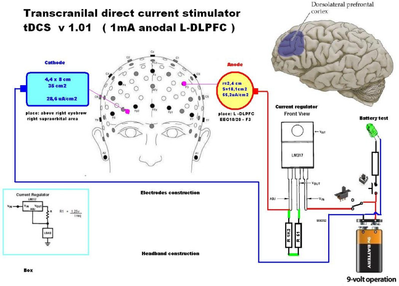
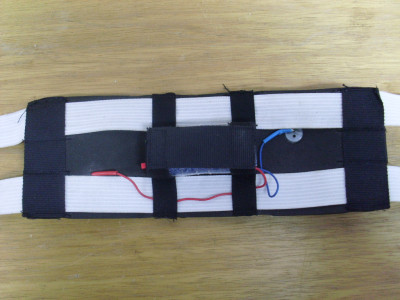
Construction of tDCS(still not complete ) *update: donut use aluminimum electrode , best is carbon TENS ,TENS with hydrogel is usable
Links to full text articles: http://www.growing.com/mind/tDCS/index.htm http://www.trans-cranial.com/research/ torrent from reddit
*this is picture of old version newer is on manual ,electrodes size and poisition is count only for electrode current density not for current density in the brain and fieled orintation.I working on new better model.
Aplications :
For long term use must be considered side effect form reference electrode and current path in the brain (and many more) ,poreblem is clinical studies didnt look for this effects.
PREFRONTAL CORTEX
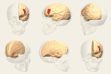
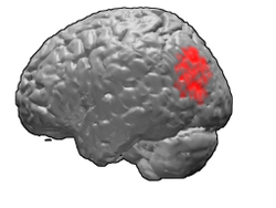
L-DLPFC
- depression
- memory
- attention
- emotional pain
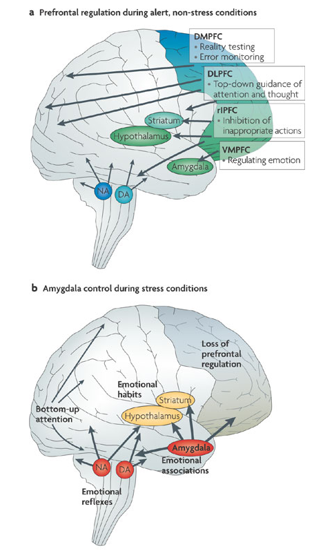
- conscious modulation of preception filtres and limbic system
Motor cortex
- pain
- improve motor learning
Pj2hGFBPmfY
- look how unfocal standart tDCS is clinicians wrongly suppouse max density uder the anode (standart motor cotex placemet)
Somatosensory cortex
TPJ (gyrus angularis)
Left and right anterior temporal lobe
Device
More precize current setup
*potentimeter + ammeter
Ramping
*trimmer *capacitor
PC on/off control
optocoupler
Automatic ramping
PC setup
HD-tDCS
PC controlled universal neurostimulator
HD-tDCS gels and electrodes
Definition of problem== How to make HD-tDCS device and what electrodes and gels use ?
EKG electrode
est of EKG elctrodes resistance With my multimettr is imposible mesure it directly so must measure volatge nad current and count the resitaence.
I test it in my 18V tDCS
EKG electrode S = 3,14 cm2
worst case scenarios
1. 2times resused EKG electrode and no skin prepation - in mastoid pacement
- I=100uA U=17,75V I=32uA/cm2 R=200kOhm feeling - nothing
2. 3resused EKG electrode and no skin prepation - DLPFC pacement
- I=50uA U=17,75V I=16uA/cm2 R=355kOhm feeling - nothing
best case scenario
1. New elctrodes + skin preparation(wash,degreased ,slight abrasion,slght wet) DLPFC placement I=2,6mA I=826uA/cm2 R=below 7kOhm device be setup for 2,6mA current density be pretty high turn it off right after I read data senstation -twitching muscele and strong fosfen in start slight burning sensation. Effects slight mood imporvement ,no rednnes in the skin.
EKG electrode problem i do some test with EKG electrode 3,14cm2 ,1mA , 318uA/cm2 ,+ on L-DLPFC and - on FT10 (left temporal below the hairline) I try severel things one of them is usage of high current density in electrode 318uA/cm2 , this is show no problem if i rmap is slowly i feel needles on a skin for about 20s and after this nothing(skin been prepared before put electrode).
I left electrode stick to head for 24h and try another stimulation i be curious about waht do skin below electrodes and how sweting and other thiong change function.A ramp it up and strat feel needles so i lowering it down try little adjust electrode contact in tect try is be better but still the feeling start before reach full current.I use setup for about 6min in lower current (without feeling).Resul of this test shows something is wrong and alectrode have bad contact.
Examinatin of electrodes cathode lost color normaly is back noe have metal color gel have brown color and little bump maybe bubble.Anode looks normal. This is a problem i plan use Ag/AgCl disk or whole ekg elctrode as HD-TDCS this electrochmicl decompositions means i need use other type.The lectrode is been used for about 25min with large current density with lower can be this effect slower.Theoreticly electrode may work afther this prety weel and problem be probably caused by little bump (different gel my help) and sweting . Some Ag iont maybe go to skin but this is no poroblem maximaly i turn blue (like some guy used to much coloidal silver) the steal below Ag coating may act as electrode weel but the bubble/bump is a large problem its posible it lowering contact area to the skin nad chnged current didtribution in the gell. After test is skin uder lectrodes little red this disapears aftef about 15mins redness is be higher uder catode.
10/10 placemet or better targeting
Definition of problem
How to find specific location ? How to make a 10/10 precize electrode cap?
Theory Postup zapojení EEG v Brmlabu (10/10 EEG placement)
TESTING :
Subjective testing
Normal - only turn it on and wait for effect
For me the most important first to determine whether it has any noticeable effect on my consciousness, even if it be only a placebo. If I get effect will be the next phase - more scientific testing.
TEST 1
- (In fact about 40s but previous tests were from an earlier apparatus and/or were not documented)
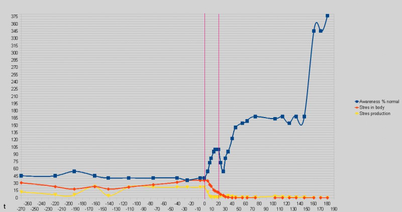
- 20 min stimulation of DLPFC (t 0-20)
- 25.10 2011 17:06 - 00:36
At the beginning (t -270-0) i was tired poor concentration and stiff neck .My situation is continuously improved in the course of stimulation i was more aware of surroundings and body ,my concentration improved,fatigue disappeared bud my neck is still little stiff.About 2 mins after stimulation i was almost back in same state that there in the begining.Notice the red line is the stress in the body (mostly stress hormones and negative emotion part of limbic sistem)they block the increase of alertness and it may also start feedback loop leading to fatigue and depression. Small amount of it is enough to block an increase in awerness above normal levels only a strong stimulation overcomes thers effect. Only way out is stop their production and start cleaning , tDCS do this job for us.After all the stress from the body disappeared awerness began to rise again and a lot more than before .In t 160 very fast change of perception and i began to smile.Production of stress is at 0 maybe this made the change -more research needed . t 180 I smile a lot ,i more aware colors are colorful shapes sharper and the world and somehow more interesting . No I'm not on drugs only tDCS :).Data ends at t+180 i must go to sleep.
hups litle problem with smooth lines in the graph
TEST 2
- 26.10 17:07 - 22.30
- 30 min 1mA L-DLPFC
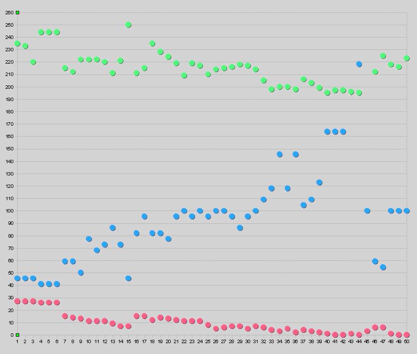
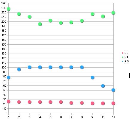
I have added measurements of reaction time, not very reliable but at least something for next time find a better program for masuring it. http://www.humanbenchmark.com/tests/reactiontime/index.php
- raction time average of 10 trials in ms
- next time explore the strange peaks in production of stress ,part of stres possible from reaction time test.
only for distinguish whether these are stimulating effect or just a learning curve
Best post tDCS (not in graph because only 5 trials ) average 182.2 ms.
- 190
- 191
- 164
- 187
- 179
Testing reaction time in the morning it went much better than yesterday. Probably thanks to the consolidation of memory / learning, or perhaps long-term effect tDCS (need more data).
- best hit was 142ms
TO DO
Blind - if i dont know its turn on or off
- find best protocol
- make version with extrenal switch
- find someone to control it
Objective testing
- Find methods:
- cognitive and other testsBrain Workshop - a Dual N-Back game The PEBL Psychological Test Batteryquantified-mind
- measurment EEG,GSR,EKG,EMG,RESP..
fNIRS Prefrontal hemodynamic changes produced by anodal direct current stimulation
- (A-active 0,28uA/cm2 A-Fp1 C-Fp2 10min+16s 8s ramp,B-sham 30s+16ds ramp(8+8))
LINKS
Comercial devices links
Updates
21.3 some new info for lucid dream induction poroject
- 5Hz anodal theta-tDCS on F3 in REM induce incerease in gamma band similar to that measured in lucid dreams
7.5 notes after closer study i move this to texts document and propper parts of site Neurophysiological Effects of Transcranial Direct Current Stimulation
TIME 5- and 7-minute tDCS results in after-effects lasting for no longer than 5 minutes, 9- to 13- minute tDCS results in after-effects lasting from 30 to 90 minutes, respectively (Nitsche & Paulus, 2001). Therefore, when we discuss electrophysiological effects of tDCS it is important to distinguish between: (1) immediate effects (e.g., anodal tDCS as excitatory, cathodal tDCS as inhibitory); and (2) the after-effects of stimulation (e.g., facilitation vs. inhibition of activity) as they may be related to different mechanisms of action (e.g., membrane vs. synaptic mechanisms).
- probably 1mA/35cm2
REPEATING While the above neurophysiological studies only examined variation in duration of a single session of tDCS, behavioral evidence suggests that repeating sessions of tDCS over several consecutive days can enhance the effects of tDCS as well (Boggio, Nunes et al., 2007). Boggio et al. (2007) examined improvement of motor performance in stroke patients following four weekly sessions of tDCS and five consecutive daily sessions of tDCS. In both experimental paradigms, they found significant motor function improvement after either cathodal tDCS of the unaffected hemisphere or anodal tDCS of the affected hemisphere when compared to sham tDCS. Importantly, while they did not find a significant cumulative effect associated with weekly sessions of tDCS, consecutive daily sessions of tDCS were associated with significant improvement over time that was sustained for 2 weeks after treatment. Future neurophysiological studies should confirm whether the neuromodulatory effects of tDCS could indeed be enhanced by consecutive daily sessions.
Cortical Silent Period
- info in study , no current data
Paired-Associative Stimulation
Wolters et al. (2003) showed that PAS increases or decreases motor cortical excitability (as measured by MEPs) when the interval between peripheral nerve stimulation and subsequent TMS pulse is 25 ms and 10 ms, respectively. This PAS-induced plasticity appears to be NMDA-receptor dependent and has been shown to influence motor learning (Stefan et al., 2006; Wolters et al., 2003; Ziemann, Ilic, Pauli, Meintzschel, & Ruge, 2004).
Nitsche et al. (2007) explored whether tDCS-induced background network activity changes effect PAS-induced plasticity. They hypothesized according to homeostatic plasticity theory that the effect of PAS would be enhanced with decreased background activity (Nitsche et al., 2007). Administering the PAS protocol to 12 healthy subjects, Nitsche et al. (2007) slowly stimulated the right ulnar nerve at the wrist at an intensity 300% above sensory threshold while a single TMS pulse was delivered over the contralateral motor cortical region representing the right abductor digiti minimi muscle. This protocol was performed alone, following anodal and cathodal tDCS, and simultaneously with anodal and cathodal tDCS. When administered simultaneously with PAS, excitability-enhancing (anodal) tDCS decreased the efficacy of PAS and excitabilitydiminishing (cathodal) tDCS increased the efficacy of PAS.This same effect was observed for prolonged administration of tDCS as well, but was not observed when tDCS was administered before PAS. This suggests, in accordance with theories of homeostatic plasticity, that tDCS has the potential to modify the efficacy of PAS by modulating background activity in the brain. For instance, decreased excitability of the cortex induced by cathodal tDCS, when applied in combination with PAS, has the potential to increase associative synaptic plasticity. *more in study ,find articles
tDCS on conditions such as chronic pain may shed light onto the neurophysiological mechanisms underlying these effects (see Zaghi et al., 2010, for recent review of the clinical applications of tDCS).
11.5 REWRITING A SITE IN PROGRESS
7.6 bulding new headsets for tDCS ad HD-tDCS (4×1)
10.6 new pictures : http://orlin.rajce.idnes.cz/tdcs
15.1 2013
- Bonsai (write them they send back password)
- starstim link
Open tDCS http://www.diytdcs.com/2013/01/the-open-tdcs-project/ https://upverter.com/opentdcs/
17.1 2013
- new site with resources about tDCS http://www.alltdcs.com
6.3 2013
- Voltage ripple poroblem in the ActivaDose II device
http://speakwisdom.wordpress.com/2012/12/29/tdcs-does-ripple-voltage-matter/
- Trought the wormhole about tDCS
I13IOKfeLzw
- Dave Siever from Mind Alive Inc.gives an overview of tDCS, how it’s theorized to work, and includes a set of tDCS montages for various purposes.
http://www.diytdcs.com/2012/11/dave-siever-mind-alive-revisited
7.3 2013
- Open Source Hardware TDCS (based on LM334Z)

 https://nocko.se/2012/07/30/brain-zapping-is-fun/
https://github.com/nocko/tdcs/
- Soterix Medical - 4×1 multichannel stimulation Device (good look to the soterix HD electrode)
6y9aG30Rpzg
8.3 2013
 The v4 is designed to drive higher impedance electrodes in addition to the usual sponge+saline electrodes by using the LT1026 charge pump controller to produce +18V to -18V split source from a 9V battery. It uses the LM334Z IC for fine current limiting control and a JFET as a gross 5mA limiter in case of LM334Z failure. ESD protection comes from two varistors. from:http://wiki.hacdc.org/index.php/TDCS
12.3 2013
Ramping capacitor - possible problem
- Yesterday i was bulding some tDCS with LM334 and try for first time use ramping capacitor. When i test device with load (5KOhms) all was ok ramping when i turn device on and ramping down when off. But when i change load (5kOhms potentiometer) during stimulation (testing) it create current peak up to 5 mA. I test it with few different capacitor and behavior is allwayes the same (only diffrent value of peak nad the time to return to normal ). Device without capacitor work witkout poroblem. In result of this i use instead of capacitor serail load ( linear potentiometr 100kOhms ) allows me to do manual ramping (0,07mA to setup current).
My question is can anybody test this capacitor problem maybe i do semething wrong , bad multimetter etc.. . If is this problem real is very bad idea use capacitor for ramping in use the resistance change is not to quick but stil can cause pretty high current peaks.
New posibilities for electrodes material NOT TESTED only ideas :
- Polyimid resistive foil (50um , 100 Ohm/cm2 ) http://www.gme.cz/vodive-pryze/polyimidova-odporova-folie-26x20cm-100ohm-p661-130/
7.4 2013
Prof. Marom Bikson “Using Computational Models in tDCS Dose” http://www.diytdcs.com/2013/04/prof-marom-bikson-using-computational-models-in-tdcs-dose/
- about problems with extracephalic electrodes
- HD-tDCS electrodes - not use saline soaked sponge -) risk of burn
- i plan test skin tolerability and sensation limits for sponge based HD-tDCS electrodes
- direction of current (in , out , tangental , radial)
- Comparing cortical plasticity induced by conventional and high-definition 4×1 ring tDCS
- time course difference , longer effect
- focality of HD-tDCS
- Inter-subject variation in susceptibility >2x in TES
- Dose normalization: Determine role of individual variation and predict requisite adjustments in subject
specific dose.
Comparing cortical plasticity induced by conventional and high- definition 4×1 ring tDCS: a neurophysiological study Brain Stimulation 2012 Kuo HI, Datta M, Bikson M, Minhas P, Paulus W, Kuo MF, Nitsche MA
8.4 Test of HD-tDCS electrodes
- problem with contact to polyimide foil
- current desity with no pain/tingeling
- 270 uA/cm2 for saline soaked sponge
- 320 uA/cm2 for TEN20 EEG gel
- (3,14cm2 electrodes on skin , cleaned by alcohol pad and abrasion by nuprep )
- voltage problem after skin preparation 8,3 V at 1mA (9V power suply ) to close to the device limit
- ——-) rebuild device to 18V version
9.4
- rebuild to 18V version
- too strong abrasion by nuprep -) increased pain in stimulation (damaged skin by abarasion)
- current desity test up to 620uA/cm2
- its posible stimulate with 620uA/cm2 without any fealing but result are not stable and is needed electrode improvements
- better result for EEG gel than for saline soaked sponge
- saline soaked sponge : not even saline distribution ? , to dry ? —) more tests
to do:
- rebuild electrodes from 3,14cm2 to 4 cm2 ( to reduce current density , new info : soterix use 4cm2 ,easier counting of current density )
- lower height of elastic ring around electrode for EEG gel electrodes ( too much consumption of EEG gel )
- sponge electrodes : Filling tube for guaranteed the same moisture for whole stimulation
- sringe
- gravity autofilling (3cm filling tube)
- head movement caused spillage ? , end of the tube ?
- improve elastic ring (reduce spillage of saline)
- electrode cap for M1/SO 35cm2
- fixation to holder
- faster shape adjusting
- electrode cap for 4×1 M1 HD-tDCS
- EEG gel electrodes adhesion : usage witout cap ?
- EEG electrode cap for 4×1 M1 HD-tDCS
- hair problem in EEG cap –) find something to move away hair
- holder allows one by one electrodes adding (easier to move away hair than in version where all electrodes fimly fixed to 4×1 holder)
- TESTS painless/sesationless current desities for all types of electrodes , alcohol Y/N ,abrasion Y/N , alcohol + abrasion
- arm or leg , forehead, hair area
- few interesting designs of caps
http://biomedicaloptics.spiedigitallibrary.org/article.aspx?articleid=1567852
- dry electrodes
- HD tdcs dry electrodes are crazy idea but worth some tests like current desity without iritation and hi-frequenci pulsed TDCS (4khz)
- comercial EEG dry electrodes
11.4
rebuild electrodes from 3,14cm2 to 4 cm2 ( to reduce current density , new info : soterix use 4cm2 ,easier counting of current density )rebuild to 4,9cm2
lower height of elastic ring around electrode for EEG gel electrodes ( too much consumption of EEG gel )OK (ring from tape)sponge electrodes : Filling tube for guaranteed the same moisture for whole stimulationOKsringegravity autofilling (3cm filling tube)Change of designhead movement caused spillage ? , end of the tube ?OK (capilar effect)improve elastic ring (reduce spillage of saline)OK
electrode cap for M1/SO 35cm2OKfixation to holderOKfaster shape adjustingOK
*electrode cap for 4×1 M1 HD-tDCS
EEG gel electrodes adhesion : usage witout cap ?OK- holder allows one by one electrodes adding (easier to move away hair than in version where all electrodes fimly fixed to 4×1 holder)
EEG electrode cap for 4×1 M1 HD-tDCS hair problem in EEG cap –) find something to move away hairHole in cap is too small to put in electrode from top- TESTS painless/sesationless current desities for all types of electrodes , alcohol Y/N ,abrasion Y/N , alcohol + abrasion
- arm or leg , forehead, hair area
TO DO
- elstic rings
*filling tube
*elctrode holder
*HD-TDCS cap
- TESTS
29.4 Usefull tool for locating DLPFC
An efficient and accurate new method for locating the F3 position for prefrontal TMS applications
http://www.ncbi.nlm.nih.gov/pmc/articles/PMC2882797/
http://clinicalresearcher.org/F3/
My Email ORLIN1@seznam.cz
