Table of Contents
OsmoBOX, the ultimate Osmocom phones driver
Abstract
This document describes implementation of a “GSM Box” - an inconspicuous box that looks like an external USB harddrive, that actually contains 4 or 8 OsmocomBB phones and a watchdog that automatically loads supplied firmware and resets phones when the firmware freezes. Additional hardware is a wideband GSM amplifier to catch traffic even from more distant handsets (work in progress). Cirtuit diagrams, board design, source code and CAD files are provided under GPL.
Designing of this box showed to be a non-trivial engineering problem, so we hope releasing this material will save others people time and energy by avoiding them from making common pitfalls.
Preparing the phone
Decap everything, later you can also strip (using a knife and moderate force) the display and LEDs to conserve power.
Use a sharp knife to remove the round metal plate from the power button.
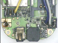
If you don't want to bother with these 2.5mm jacks, you can either strip the 2.5mm jack connector at all (you will then need to solder to small soldering pads) or better cut the upper half of it. Use a sharp knife, little pliers or a tweezer. See, what happens when you plug in the jack (i.e. what contacts are shorted) and short them too.
Use sandpaper and then tin the inner circle of the button, battery terminals, ground contact of the pager motor and the serial port pads. Use as much soldering flux as possible.
Then solder your favorite 5-pin (button, GND, Vcc, Rx, Tx) connector. For our first prototype we used header and female cable connector for it and it sucks. Visit your local electro store and look for something better.
The Phone
A c123xor phone has the following interesting terminals:
- BAT+ terminal (inner)
- BAT- terminal (outer)
- Common ground (COM) (shielding, outer JACK connector and almost all ground plate on PCB)
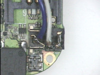
- 3.3V serial port in an audio jack. Phone's Tx is white cable on the photo above, Rx is blue.
- Power button (red one)
Under normal operation, common ground is at +0.6V (given BAT- as a reference). This means that BAT- is not connected with the serial port GND. However, we are powering the phone from an external 4.3V power supply and we shorted BAT- with COM and it wowks fine. Mechanically, this can be best done by connecting BAT- with “-” terminal of the pager motor. Multimeter is your friend.
Pressing the power button
Unpressed button = the inner circle is electrically floating.
Pressed button = the inner circle is grounded (LOG0).
Powering the phone
When you have the serial connected, the phone is automatically grounded (when powering it from USB and using FTDI, V- is connected to serial GND). However, as this grounds only COM and not BAT-, some features (especially buttons) don't work. This is why you need to short COM and BAT-.
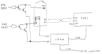
We finally (after several nights of debugging) settled on the following schematics that seems to be working now.
The Darlington switch is actually ULN2003A. Single NPN transistor could be used too (peak current is about 200mA), FET probably too. Using Darlington has one disadvantage - the whole phone is at +0.6 (single silicon junction). Fortunately, our FTDI discriminates +0.6V as a correct LOG0.
Note on USB hubs and cables
Some USB hubs have a diode between input and output V+. There is a voltage drop of about 0.4-0.5V. Just short the diode, we don't want this drop.
Another voltage drop is on USB cable. Manufacturers tend to save copper, so they use very thin wires. I have seen a cable that had 2 ohms! This is drop of 0.8V at 400mA! The symptoms were simple - two or three phones worked, other didn't. Original FW was complaining about empty battery. Btw. osmocom Hello World FW measures the voltage too. Or just use your voltmeter…
Driving BTN_DRIVE and PWR_DRIVE
You need 2 GPIO pins for each phone. Trivial approach was to use DTR/RTS signalling from the FTDI serial port. Unfortunately, when you touch it (disabling hardware control flow), there pins are reset. This could be a driver issue, but we didn't want to hack the kernel driver. We decided to debug it on an Arduino shield and later, it will be probably drived by a standalone ATmega.
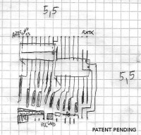
This is the first prototype, drawn by a flipchart marker and then etched; ULNs are surface-mounted. It's a disaster, but it works. Notice the Ultimate Debugging LED™.
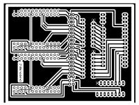
Much better is the current PCB. Eagle files can be obtained from Github or here is a 300DPI PNG. It is driven by Arduino Nano and it supports 8 phones.
There is unfortunately one HW bug. Our Nano from DealExtreme has too narrow trace for USB V+. Therefore, running more than ~4 phones will cause voltage drop. This can be fixed by connecting USB V+ from your USB hub with the main Vcc trace on the board.
Phones are connected using 40-pin IDE connector. Phones can be either soldered or on connectors.
Please download this handy reference to avoid stroke when studying official vendor's manual.
When done properly, all this should fit into 3.5“-harddrive-like box. Phones are isolated using a plastic bag.
Driver protocol
Firmware source code is on GitHub
brmboractl, gsm_init_hw and motoload are user-space tools used to manage this. TODO solve license problems with them and publish them (you can speed this up by carefully dropping us an e-mail :)
–
Fire up your favorite terminal and begin the communication.
# Minicom configuration
pu port             /dev/ttyFFFFUUUU
pu baudrate         9600
pu rtscts           No
- ”-“ cleans the buffer
- CR, LF or @ executes the buffer
- no backspace, history or command-line editing implemented
- The only implemented command is “s”
- Syntax: sx1
- x … pin letter (documented on the paper somewhere in brmlab)
- 1 or 0 … on/off
- e.g. to turn on the LED, send “st1@”
When controlling from bash (echo bah > /dev/ttyUSB0), make sure you have echoing on your serial port turned OFF! stty -F /dev/ttyUSB0 -echo
Upstream Filters
Antenna
Amplifier
People
- Jan Hrach (jenda .a. hrach.eu)
- Řehoř Gölöncséryi (niekt0 .a. hysteria.sk)
- License:
