Table of Contents
Galvanic Vestibular Stimulation
- not ment for long term usage (unknown risk of undisaired neuromodulation)
mastoid:

info:
http://jap.physiology.org/cgi/content/full/96/6/2301
http://jn.physiology.org/cgi/content/full/85/2/886
http://jn.physiology.org/cgi/content/full/96/2/925
http://jn.physiology.org/cgi/content/full/95/5/3199
http://www.eccentricgenius.com/wp/2006/05/17/bipolar-binaural-galvanic-vestibular-stimulation/
http://jp.physoc.org/content/551/3/1033.full
http://juwel.fz-juelich.de:8080/dspace/bitstream/2128/2536/1
Notes
- falling towards the side of the cathode
- The stimulus is most commonly delivered with an anodal electrode on the mastoid process behind one ear and a cathodal electrode behind the other ear, i.e., bilateral bipolar GVS. However, other configurations are bilateral monopolar GVS with electrodes of the same polarity at both ears and a distant reference electrode and unilateral monopolar GVS with a stimulating electrode at just one ear. When the small current flows for 1 or 2 s, it causes a person to sway if they are standing or perceive illusory movements if they are not. The simplicity of the technique, however, belies the complexity of the body response it evokes.
- Discharge rates. In all species studied, the vestibular primary afferent neurons, which innervate the cristae and maculae, discharge spontaneously at rest when no stimulus is applied. This means that, with rate coding, a neuron can respond to accelerations in both directions. (90–115 s-1 in macaque monkeys)
- Sensitivity. Afferent firing rates increase or decrease depending on amplitude and direction of an imposed acceleration. For the squirrel monkey, this dynamic range is 0–300 s-1 at about the 65–90 s-1 resting discharge rate, with an average gain or sensitivity of 2 s-1 per deg·s-2 for the semicircular canals and 33 s-1/g for the otolith organs (27, 40). On average, irregular neurons have slightly lower tonic rates than regular neurons but are more sensitive to acceleration stimuli and have shorter refractory periods than regular neurons. The response of regular units is predominantly tonic; that of irregular units tends to be more phasic. Responses are greater for excitatory than for inhibitory stimuli, particularly for irregular units. As might be expected in a system where a continuous discharge is modulated, there does not appear to be a threshold value in these responses; they are continuous about the resting values. Adaptation in the primary afferents with a sustained acceleration stimulus is mixed. In some units, adaptation is clear, particularly to inhibitory stimuli, whereas many units show no adaptation. Adaptations of behavioral responses, such as the vestibuloocular reflex, are greater than adaptations seen in the afferent or vestibular nuclei, implying that much of the adaptation occurs further down the reflex pathways (14).
- GVS can be considered to modulate the hyperpolarization of the neuroepithelia of the cristae and maculae.
- GVS will alter the firing pattern of canal afferents in a way that has no natural rotational equivalent. Cathodal GVS will increase the firing rate of all responsive afferents, regardless of their direction specificity. Thus, for the horizontal canal, this would signify a natural yaw with the nose moving toward the ipsilateral, or cathodal, side (Fig. 1, left horizontal canal). The same increased firing induced by cathodal GVS in afferents of the anterior and posterior canals will signify ipsilateral ear-down roll, and the signals from both canals should add (Fig. 1, left of roll; the canals overlap in this view). Because they are aligned at 45 deg to the sagittal axis of the skull, the anterior canal will also indicate nose-down pitch and the posterior canal a similar nose-up pitch (Fig. 1, left of pitch). These opposing signals have no natural equivalent and should cancel because they are equal in size and opposite in direction. Thus, considering all three canals, the pattern of afferent discharge evoked by GVS will signal rotation with yaw and roll components relative to the plane of the vestibular apparatus. Furthermore, the roll component should be larger than the yaw component because of the vector addition of signals from both vertical canals.
- To complicate matters, the canals are not aligned in the plane of the head and are not quite orthogonal so they will not add and cancel quite as neatly as this model suggests. The entire canal structure tilts backward by ∼30 deg from the head horizontally, and this gives the horizontal canals a roll component at the expense of yaw. The vertical canals develop a yaw component at the expense of roll, while maintaining sensitivity to the pitch component. Fortunately, however, we can calculate the vector for each canal because their planar relationships relative to Reid's stereotactic line (inferior orbital rim to auditory canal) have been accurately measured

- Fig. 2.
Vector summation of semicircular canal responses to GVS. Vectors of unit amplitude are plotted orthogonal to the plane of each canal (a, p, and h), referenced to Reid's stereotactic plane (broken line). Lateral and vertical components are in the front view; sagittal and vertical components are in the lateral view. The resultant vectors ® for each labyrinthus are shown as white arrows. The vector sums of the resultants from each side are the large white arrows (L+R), and the curved arrow shows the right-hand rule representation of the vector direction. A: Bilateral bipolar GVS, anode right. The canal vectors are superimposed in the lateral view. GVS vectors sum to produce a large roll component and a yaw component. The pitch components cancel. B: bilateral unipolar GVS, anodal. The canal vectors are in opposite direction in the lateral view. GVS vectors in roll and yaw cancel, leaving a small residual pitch vector, directed backward for anodal current. C: three-dimensional sketch of the right anodal GVS vectors for each canal, to assist orientation. *See text for explanation.

- Fig. 4.
Summation of the lateral components of utricular signals. The utricular maculae with the head for orientation are shown. A: with the head stationary and level, all afferents will maintain their tonic discharge (dot density). Thus the pars lateralis and pars medialis produce acceleration signals in opposite directions, indicated by the white and gray arrows respectively. Because pars lateralis is slightly larger than pars medialis, the net signal from the utricular macula will be a small lateral acceleration. However, the signal from the contralateral macula cancels this, resulting in a net acceleration signal of zero (S0). B: when exposed to a lateral acceleration toward the right, or tilt to the left, the discharge from the left pars medialis and the right pars lateralis increases and that of the left pars lateralis and right pars medialis decreases. Thus both sides sum to produce the large net acceleration signal (SA). C: on the left, anodal GVS decreases the firing rate of the pars medialis and the pars lateralis afferents. Cathodal GVS on the right increases the firing of the entire population. On each side of the head, the signals almost cancel. Only the small size discrepancy between the pars medialis and pars lateralis populations results in a small net acceleration signal (SG). *http://digitalcommons.calpoly.edu/cgi/viewcontent.cgi?article=1239&context=theses *Types of Stimulation Yaw, pitch, and roll sensations are generated through different galvanic vestibular stimulation techniques. Uni polar, bilateral bipol ar, and bilateral unipolar stimulation are common configura tions for generating sensations [8]. Figure 5shows a sample diagram of the el ectrode configuration used at the Mayo Clinic and in our experiments to gene rate orientation sensations. The five electrodes use a combination of unipolar, bilateral bipolar, and bilateral unipolar stimulation to generate the orientation se nsations. Each electrode with a number can be individually stimulated in refe rence to the common (COM) electrode. *pic page 18
3D with 2 electrodes
- imposible with DC modulate all afference at once
- pulsed DC with rate of neuronal discharge
- more test neaded
- Basic dicharge rate ?
- Have channels different discharge rate ?
- How accleration effect discharge rate?
- A normal resting discharge rate of approximately 90 spikes per second is modulated, such that increase of this rate corresponds with an excitation and decrease with Inhibition.
- The discharge rate increases in the leading right ear (e.g. from 90 to 300 spikes per second).8. The discharge rate decreases in the following left ear (e.g. from 90 to 20 spikes per second).
- The vestibular nuclei interpret the difference in discharge rates between left and right SCC as movement to the right, and therefore trigger the oculomotor nuclei to drive the eyes to the left to maintain gaze stabilization.
- regular and iregular spacing
- rates are lower for otolith
- iregular have lower rates
- discharge regularity is specific for each afferent
- 0,4 spike/s 1 deg/s
Planned usage :
Remote control human
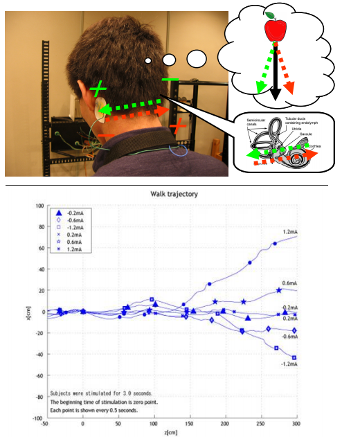
- controls the direction of human bipedal movement DONE
- + akcelerometer - balance for alcohilc Only idea i dount need this
http://www.youtube.com/watch?v=guaiDZdsDjI
http://www.youtube.com/watch?v=OlXYqfQHNuA
http://www.youtube.com/watch?v=tCLsAgPuumw
== Feel the music == PARTIALY DONE
- When the stimulation is synchronized to musical rhythms, the device provides a very amazing experience. Especially when stimulation is at a high frequency (more than 1~2 Hz), users feel as if their visual fields and bodies are tremblingly along with the rhythm.
- unipolar bilateral test DONE
- effect it not so strog bud feilable
Neuromodulation
Induction of Out of body experience
- angular and linear akceleration based ilusion
- research for OOBE aplication
Games
- problem with long term usage of bilateral montage